Home
› Indak 6 Pole Switch Diagram - Indak Ignition Switch Wiring Diagram / The dpst switch, for example has four terminals however is a double pole (dp) and not a four pole (4p) switch.
Indak 6 Pole Switch Diagram - Indak Ignition Switch Wiring Diagram / The dpst switch, for example has four terminals however is a double pole (dp) and not a four pole (4p) switch.
Indak 6 Pole Switch Diagram - Indak Ignition Switch Wiring Diagram / The dpst switch, for example has four terminals however is a double pole (dp) and not a four pole (4p) switch.. The centrifugal switch is generally shown attached to the single phase motor. Indak 5 pole ignition switch wiring diagram (nov 22, ) ― You can easily add switches, appliances and connect them to create your circuit diagrams within minutes. March 22, 2019march 22, 2019. The other one had the hot wire on the 3 way side which was not in the diagram.
Rule a matic float switch wiring diagram. To open or close a single wire connection between a power source and a load. Our modular technology allows us to build custom switching solutions for up to 24 poles! Several terms are used to describe switch contacts: You can easily add switches, appliances and connect them to create your circuit diagrams within minutes.
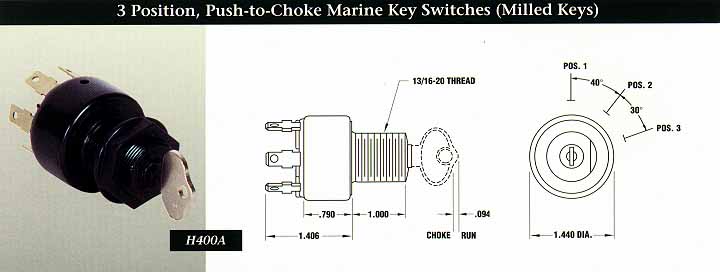
2 Position Marine Key Switches Milled Keys Indak Switches from www.indakswitches.com 1.7 mib 16298 downloads details. You can easily add switches, appliances and connect them to create your circuit diagrams within minutes. The centrifugal switch is generally shown attached to the single phase motor. Our modular technology allows us to build custom switching solutions for up to 24 poles! The symbols can be rotated and resized. In this video i showed motor rewinding 36 slots 3 phase 6 pole with diagram. Uxcell 5pin 1p4t 1 pole 4 position selectable 1 deck band selector rotary switch 2pcs. Several terms are used to describe switch contacts:
In electrical engineering, a switch is an electrical component that can disconnect or connect the conducting path in an electrical circuit, interrupting the electric current or diverting it from one conductor to another.
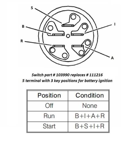
Indak 5 pole ignition switch wiring diagram (nov 22, ) ― The other one had the hot wire on the 3 way side which was not in the diagram. This indak 5 pole ignition switch wiring diagram photo have been authored. In this video i showed motor rewinding 36 slots 3 phase 6 pole with diagram. 6 p switch schematic diagram and connection method: Wiring diagramindak 6 pole ignition switchindak 5 pole switch6 pole ignition switch wiringindak ignition switch 2868906ignition switch 3497644 wiring. You can easily add switches, appliances and connect them to create your circuit diagrams within minutes. The dpst switch, for example has four terminals however is a double pole (dp) and not a four pole (4p) switch. , grounding diagram transient earth clamp , type a 35 sq.mm. Here i described andcalculate all data. There are 2 rows of pins, 3 pins in each row, the middle one is the common terminal, corresponding to the two left and right pins, one is normally open and the other is normally closed. With ammeter shown in optional position, note that − and + symbols are reversed. March 22, 2019march 22, 2019.
The white wire of the romex going to the switch is attached to the black line in the fixture box using a wirenut. If you new and want to learn induction. You can easily add switches, appliances and connect them to create your circuit diagrams within minutes. March 22, 2019march 22, 2019. Rule a matic float switch wiring diagram.
Indak 6 Prong Ignition Switch Wiring Diagram 2014 Honda Odyssey Wiring Diagram Begeboy Wiring Diagram Source from www.wheelhorseforum.com In this video i showed motor rewinding 36 slots 3 phase 6 pole with diagram. The centrifugal switch is generally shown attached to the single phase motor. The dpst switch, for example has four terminals however is a double pole (dp) and not a four pole (4p) switch. Pole should not be confused with terminal. 2bulbs #1singlepoleswitch this a a tutorial video or diy on how to install two bulbs controlled by one single pole switch. To open or close a single wire connection between a power source and a load. Uxcell 5pin 1p4t 1 pole 4 position selectable 1 deck band selector rotary switch 2pcs. Switched reluctance drives with degraded mode.
A wide variety of 6 pole switch options are available to you, such as function, certification, and customized.
Uxcell 5pin 1p4t 1 pole 4 position selectable 1 deck band selector rotary switch 2pcs. 1.7 mib 16298 downloads details. Here i described andcalculate all data. , grounding diagram transient earth clamp , type a 35 sq.mm. 3 pole 6 position three decks 21 terminal band channel rotary switch with cap. 848 results for 6 pole switch. To write a wiring diagram for a capacitor start motor, all connections must be clearly labelled. 2bulbs #1singlepoleswitch this a a tutorial video or diy on how to install two bulbs controlled by one single pole switch. Skip to main search results. March 22, 2019march 22, 2019. With ammeter shown in optional position, note that − and + symbols are reversed. The white wire of the romex going to the switch is attached to the black line in the fixture box using a wirenut. How to wire a single pole light switch, in this video we look at how a single pole light switch works and the different ways to wire a.
March 22, 2019march 22, 2019. Switched reluctance drives with degraded mode. 6 p switch schematic diagram and connection method: 848 results for 6 pole switch. Single pole switch diagram #2 this switch wiring diagram shows the power source starting at the fixture box.
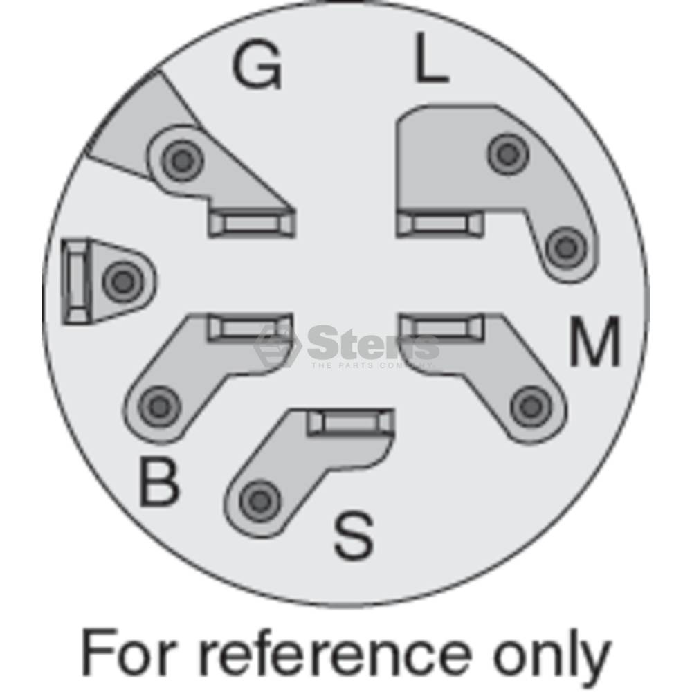
Indak Ignition Switch Wiring Diagram Tstat Wiring Diagram Begeboy Wiring Diagram Source from www.stens.com In electrical engineering, a switch is an electrical component that can disconnect or connect the conducting path in an electrical circuit, interrupting the electric current or diverting it from one conductor to another. 6 p switch schematic diagram and connection method: Here i described andcalculate all data. Most common one is the asymmetric bridge converter, comprising two switching devices and two power diodes per phase. Double pole double through turns on and off two circuits at the same time using a common lever. Indak 5 pole ignition switch wiring diagram (nov 22, ) ― To write a wiring diagram for a capacitor start motor, all connections must be clearly labelled. Rule a matic float switch wiring diagram.
They not only control lights but other electronics too.
3 pole 6 position three decks 21 terminal band channel rotary switch with cap. Our modular technology allows us to build custom switching solutions for up to 24 poles! The centrifugal switch is generally shown attached to the single phase motor. I finally realized i needed to split the circuit and put the hot on the black terminal, it just would have been nice to know that from the start. Several terms are used to describe switch contacts: Took me a while of looking at how the switch worked to really get it. They not only control lights but other electronics too. To write a wiring diagram for a capacitor start motor, all connections must be clearly labelled. With ammeter shown in optional position, note that − and + symbols are reversed. The white wire of the romex going to the switch is attached to the black line in the fixture box using a wirenut. Double pole double through turns on and off two circuits at the same time using a common lever. Pole should not be confused with terminal. Most common one is the asymmetric bridge converter, comprising two switching devices and two power diodes per phase.