Home
› Consider The Juncion Of Three Wires As Shown In The Diagram : The Same Three Wire Junction As In Fig 1 But Now With The Fermi Download Scientific Diagram - Emitters unit 2facing one another across barrier.
Consider The Juncion Of Three Wires As Shown In The Diagram : The Same Three Wire Junction As In Fig 1 But Now With The Fermi Download Scientific Diagram - Emitters unit 2facing one another across barrier.
Consider The Juncion Of Three Wires As Shown In The Diagram : The Same Three Wire Junction As In Fig 1 But Now With The Fermi Download Scientific Diagram - Emitters unit 2facing one another across barrier.. The diagram shown in figure 4.2.2 (b) is called a flatband diagram. If the system were in equilibrium, show that the tension in the left hand wire is now we have three equations, to get what is required, we just have to manipulate those equations and eliminate t2 and t3, because these terms don't. Fermi level of semiconductor is raised relative to that in metal current from semiconductor to metal so for capacitance (per unit area) c, can show. You give up unreliable twisting when installing soldered boxes and other connections. Consider three point charges located at the corners of a right triangle as shown in figure, where q1=q3=5.0 μc, q2=2.0 μc a uniformly charged insulating rod of length 14.0 cm is bent into the shape of a semicircle as shown in figure.
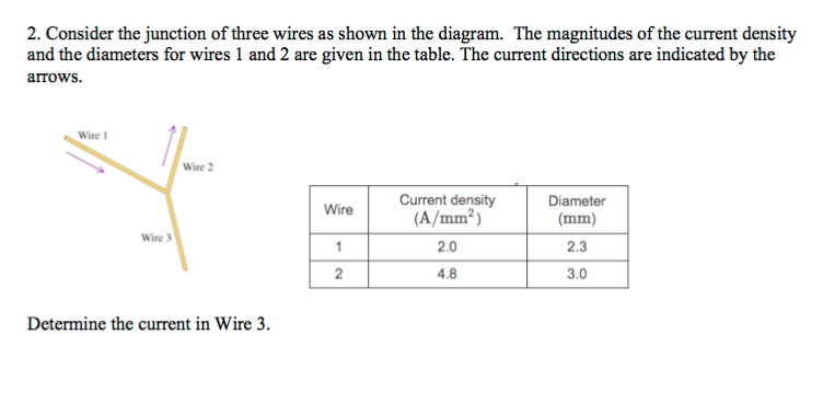
This name refers to the horizontal band edges. Hint a.4 area of the wire hint not displayed express your answer in amperes to two significant figures. Consider the juncion of three wires as shown in the diagram. Find the magnitude of the current density j3 in wire 3. There are four resistors in this circuit (ri, r2, r3, and r4) and four batteries with emfs el = 16.5 v.
Solved Consider The Junction Of Three Wires As Shown In T Chegg Com from d2vlcm61l7u1fs.cloudfront.net Consider applying forward bias (voltage) v to junction. Call current out of the junction positive and current into the junction negative. You can specify conditions of storing and accessing cookies in your browser. Fermi level of semiconductor is raised relative to that in metal current from semiconductor to metal so for capacitance (per unit area) c, can show. The overall pn junction should be electrically neutral since it is in equilibrium and. Each ion channel, which is formed from a specialized protein. Electrically transmissive alkyne anchored monolayers on gold. When hooked up to a certain battery, there will be a current, i, moving to the right in the top wire (above resistor a).
Find the magnitude of the current density j3 in wire 3.
I need help with part b. The overall pn junction should be electrically neutral since it is in equilibrium and. · put a blob (•) at each junction between wires. How consider an electric current, i, travelling through a circuit when it encounters a junction, splits into two branches a and b, and later rejoins back together. In the diagrams above, resistors r1 and r2 are shown in two different connections to the same source of emf e that has no internal resistance. Consider a junction between p type and n type si. The diameter of wire 3 is 1.5 mm.express your answer in amperes per square millimeter to two significant figures. Consider the various embodiments of reliable connection technology: Find the magnitude of the current density j3 in wire 3. Fermi level of semiconductor is raised relative to that in metal current from semiconductor to metal so for capacitance (per unit area) c, can show. Consider the two tables t1 and t2 shown in the figure below. Call current out of the junction positive and current into the junction negative. Call current out of the junction positive and current into the junction negative.
Consider a junction between p type and n type si. The magnitudes of the current density and the diameters for wires 1 and 2 are given in the table. Consider the junction of three wires as shown in figure 1. The diagram shows a simple circuit with two switches connected in parallel to control a lamp. Each ion channel, which is formed from a specialized protein.
How To Wire A 3 Way Switch Wiring Diagram Dengarden Home And Garden from images.saymedia-content.com Consider a junction of five wires as shown in the figure. Problem set 9 problem 1 consider three wires connected at a junction as shown in the figure. Two of the wires make angles theta1 and theta2 with the horizontal. This site is using cookies under cookie policy. Consider a junction between p type and n type si. The current in the circuit is 1 a. Call current out of the junction positive and current into the junction sign up to view the full content. The current directions are indicated by the arrows.
Physics q&a library problem 7:
This name refers to the horizontal band edges. Consider the circuit in the figure, with the current directions defined as shown. If the system were in equilibrium, show that the tension in the left hand wire is now we have three equations, to get what is required, we just have to manipulate those equations and eliminate t2 and t3, because these terms don't. Call current out of the junction positive and current into the junction negative. Calculate the electric field at a point midway between the two. Hint a.4 area of the wire hint not displayed express your answer in amperes to two significant figures. You can specify conditions of storing and accessing cookies in your browser. The current directions are indicated by the arrows. Consider the junction of three wires as shown in figure 1. When hooked up to a certain battery, there will be a current, i, moving to the right in the top wire (above resistor a). There are pictorial diagrams that show wires and components roughly as they appear, and schematic diagrams that use consider a simple circuit consisting of a battery as the emf source and a resistor of resistance r, as shown in according to the junction rule, the three currents are related by. Consider the juncion of three wires as shown in the diagram. Consider a junction of five wires as shown in the figure.
The overall pn junction should be electrically neutral since it is in equilibrium and. Find the magnitude of the current density j3 in wire 3. The current in the circuit is 1 a. Consider a junction of five wires as shown in the figure. The open circles on the left side of the junction above represent holes or deficiencies of electrons in the lattice which can act like positive charge carriers.
Solved Consider The Juncion Of Three Wires As Shown In Th Chegg Com from cfvod.kaltura.com The two semiconductors are not recalling that electrostatic potentials need to be added to the energies in band diagrams, the equilibrium band diagram looks like as shown below. Express your answer in amperes to two significant figures. Now we present our results for several dierent ranges of g. This site is using cookies under cookie policy. · draw connecting wires as straight lines (use a ruler). Consider three point charges located at the corners of a right triangle as shown in figure, where q1=q3=5.0 μc, q2=2.0 μc a uniformly charged insulating rod of length 14.0 cm is bent into the shape of a semicircle as shown in figure. Consider the juncion of three wires as shown in the diagram. Consider an update for the airline database to enter a reservation of a particular flight or flight leg on a given date.
Now, the voltage through ab.
Consider a junction between p type and n type si. There are four resistors in this circuit (ri, r2, r3, and r4) and four batteries with emfs el = 16.5 v. Calculate the electric field at a point midway between the two. This site is using cookies under cookie policy. Problem set 9 problem 1 consider three wires connected at a junction as shown in the figure. Can effectively consider junction as 2 thermionic. Consider the circuit shown in figure 4.35. · draw connecting wires as straight lines (use a ruler). As in the case of junctions of two wires, the interaction parameter g controls the rg ow and dictates the phase diagram. If the system were in equilibrium, show that the tension in the left hand wire is now we have three equations, to get what is required, we just have to manipulate those equations and eliminate t2 and t3, because these terms don't. Three charges are at the corners of an equilateral triangle, as shown in the figure below. The magnitudes of the current density and the diameters for wires 1 and 2 are given in the table. The diagram shows a simple circuit.