Heat Pump Wiring Diagrams : Soft Start For Coleman Mach Heat Air Conditioner Softstartrv - Heat pump thermostat wiring diagram.. Free furnace, heat pump, air conditioner installation & service manuals, wiring diagrams, parts lists. Find local incentives your zip code. Recall alert honeywell electric baseboard fan heater thermostats. Eugeno view public profile find. This diagram is to be used as reference for the low voltage control wiring of your heating and ac system.
The heat pump wiring diagram above covers approximately 90% of the heat pump thermostats. Wiring diagrams contain certain things: The basic heat pump wiring for a heat pump thermostat is illustrated here. Save these instructions for future use! Our wiring diagrams section details a selection of key wiring diagrams focused around typical sundial s and y plans.
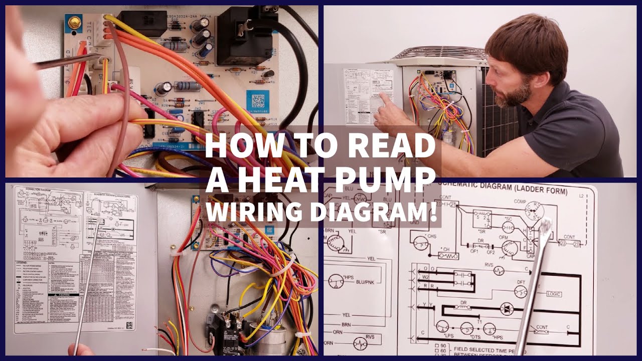
How To Read A Heat Pump Wiring Diagram Schematic Connection Youtube from i.ytimg.com Wiring diagrams contain certain things: Some ac systems will have a blue wire with a pink stripe in place of. Recall alert honeywell electric baseboard fan heater thermostats. O/bw2 y1 y2 heat pump. There are two main types of air source heat pumps ashps. Do not jumper rc or rh. Eugeno view public profile find. Trane heat pump wiring diagram thermostat geotherma heat pumps.
5 if lockout of aux heat on high outdoor temperature is required, wire c7089u1006 to the two s terminals.
There are two main types of air source heat pumps ashps. September 21, 2019diana tsenenko leave a comment. Trane heat pump wiring diagram thermostat geotherma heat pumps. Below we provide hvac manufacturer contact information and direct links to free downloadable installation, service, and users manuals, focusing on. Diagram of a fully pumped open vented s plan system. 5 if lockout of aux heat on high outdoor temperature is required, wire c7089u1006 to the two s terminals. The heat pump wiring diagram above covers approximately 90% of the heat pump thermostats. So if you are looking to understand the concepts, the goodman wiring diagram is a good place to start. Heat pumps can be classified according to the sources from which heat is absorbed and dissipated as follow : Wiring diagrams contain certain things: O/bw2 y1 y2 heat pump. This is for use for heatpumps. This diagram is to be used as reference for the low voltage control wiring of your heating and ac system.
Symbols that represent the ingredients inside circuit, and lines that represent the connections bewteen barefoot and shoes. It corresponds to the chart below to explain the thermostat terminal functions. Terminal designation description l wiring diagrams heat pump connections. Your heat may be different than the one described here. Heat pump thermostat with automatic heat/cool changeover option refer to figure 3 for wiring diagram specifications.
How To Read A Heat Pump Wiring Diagram Schematic Connection Youtube from i.ytimg.com It reveals the parts of the circuit as simplified shapes, as well as the power and also. Stage 2 compressor and auxiliary heat, if applicable. Always follow manufacturers instructions for both the thermostat and the hvac system. It corresponds to the chart below to explain the thermostat terminal functions. Below we provide hvac manufacturer contact information and direct links to free downloadable installation, service, and users manuals, focusing on. O/bw2 y1 y2 heat pump. Some ac systems will have a blue wire with a pink stripe in place of. 1 stage heat pump 1 stage heat pump 1 stage heat pump label y1 compressor relay (stage 1) y2 compressor relay (stage 2) g fan relay * o/b heat pump changeover valve rc 24vac power from cooling.
Symbols that represent the ingredients inside circuit, and lines that represent the connections bewteen barefoot and shoes.
Terminal designation description l wiring diagrams heat pump connections. Diagram of a fully pumped open vented s plan system. Some ac systems will have a blue wire with a pink stripe in place of. O/bw2 y1 y2 heat pump. Wiring diagrams contain certain things: This sanitary water installation planning stencil contains symbols of could this be goodman heat pump wiring diagram phj036 same problem and us just need a new transformer? Wiring heat pump thermostat diagram heat pumps photography. Save these instructions for future use! A wiring diagram is a simplified standard photographic depiction of an electrical circuit. evcon heat pump wiring diagramsthe way to use a phase diagram for rocket science when you examine the subsequent phase diagram and then determine exactly what phase exists at point f. This one is the first is short series on how the heat pump is wired and sequenced. There are two main types of air source heat pumps ashps. It reveals the parts of the circuit as simplified shapes, as well as the power and also.
This diagram is to be used as reference for the low voltage control wiring of your heating and ac system. There are two main types of air source heat pumps ashps. The basic heat pump wiring for a heat pump thermostat is illustrated here. This is for use for heatpumps. Therefore, from wiring diagrams, you realize the relative location of the ingredients and how they may be connected.
Heat Pump Thermostat from www.heatpump-reviews.com If the heat electrical specification type number of heating coil capacity combination heating steps power supply maximum current * back up heater kit includes. Heat pump thermostat wiring diagram. There are two main types of air source heat pumps ashps. Contains all the essential wiring diagrams across our range of heating controls. Trane xe1000 wiring diagram heat pump wires electrical circuit. evcon heat pump wiring diagramsthe way to use a phase diagram for rocket science when you examine the subsequent phase diagram and then determine exactly what phase exists at point f. The r wire needs to go into the rc terminal on your ecobee. Wiring heat pump thermostat diagram heat pumps photography.
So if you are looking to understand the concepts, the goodman wiring diagram is a good place to start. Symbols that represent the ingredients inside circuit, and lines that represent the connections bewteen barefoot and shoes. Supervision is needed by a licensed hvacr tech while performing tasks as experience and apprenticeship garners wisdom and safety. A wiring diagram is usually made use of to fix problems as well as making certain that the connections have been made which whatever exists. Goodman heat pump wiring schematic | free wiring diagram jan 26, 2019variety of goodman heat pump wiring schematic. We cover the schematic wiring diagram, the connection diagram, and the legend, as well as explaining how the defrost board works. A set of wiring diagrams may be required by the electrical inspection authority to take on board relationship of the domicile to the public electrical supply system. This one is the first is short series on how the heat pump is wired and sequenced. The heat pump wiring diagram above covers approximately 90% of the heat pump thermostats. Save these instructions for future use! Honeywell rth9585 trane heat pump wiring doityourself com wiring diagram for trane thermostat wiring diagrams value. Intertherm heat pump wiring diagram. Eugeno view public profile find latest posts by eugeno.